Selecting the proper spark gap for a particular application involves the simultaneous consideration of several factors. These considerations lead to a spark gap choice which:
This section provides a checklist for selecting a spark gap for communication circuitsand also AC and DC power circuits.
|
A. COMMUNICATION CIRCUIT APPLICATIONS Selection of a spark gap for application on communication circuits is perhaps the easiest of the three basic application problems. Most communications applications do not require any special consideration of circuit effects on the spark gap after the transient has passed because these applications normally do not have the ability to hold the spark gap in either the glow or arc region after the transient surge has passed. Communications spark gap selection involves the following five steps:
B. AC POWER CIRCUIT APPLICATIONS The method of selection of a spark gap for AC power applications is identical to that used for communications circuits except for one important difference. When the power source can supply sufficient short circuit current for one half cycle, this current and its duration must be added to the transient current waveshape in determining the duty cycle required of the spark gap. This is because the spark gap, once initiated by the transient, must carry the power source current for the remainder of that half cycle until the tube extinguishes on the next power frequency current zero. This power supply portion of the duty cycle required of the spark gap is called the ìpower follow currentî. Its amplitude is not normally significant in relation to the transient surge amplitude but at power frequencies its duration is quite long. Often in AC power applications, to permit the use of a spark gap of practical size, a small resistance (less than one ohm) or varistor is placed in series with spark gap to limit this power follow current. This resistance develops a voltage, known as the ìdischarge voltageî which is due to the transient surge current. This discharge voltage appears across the protected load and must be considered in determining the protection level achieved. A checklist for AC power circuits applications is as follows:
C. DC CIRCUIT APPLICATIONS Application of spark gaps on DC circuits provide the most challenging applications because of the inherent characteristics of spark gaps to continue to discharge as long as an arc or glow current can be provided. From the general Applications Information of pages 3 and 4 we see that unless the DC supply voltage across the spark gap is reduced to a level lower than the current-voltage relationship for the tube for a given source current, the spark gap will continue to conduct following its initiation by a transient surge. For this reason, for other than low source current DC applications and DC system supply voltages less than the arc voltage of the tube, we must supply supplemental circuit elements to assure that the spark gap will extinguish. Circuits with DC supply voltages below the arc voltage of the spark gap, or with low source currents and voltages below the glow voltage of the tube may be treated as communications circuits. For DC circuits, which cannot be treated as communications circuits, the following checklist is provided:
If the system DC voltage is higher than 100 volts the Reynolds Applications Engineering Group should be consulted due to the possibility of exceeding the glow voltage of the particular spark gap. Once a spark gap has been selected, provisions must be made to include supplemental circuit resistance to limit the DC system current through the spark gap to a value which will bring the tube back into the glow region following the passage of the surge. If this added resistance can be placed in series with the normal system load carrying conductors the transient voltage developed across the resistor will not appear across the protected load. If this added resistance must be placed directly in series with the spark gap it will also develop a discharge voltage similar to that found in the AC power circuit application of spark gaps, which will appear across the protected load. 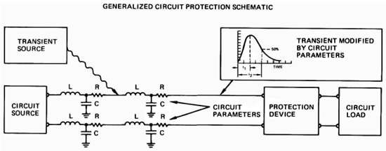 Because of the critical nature of these extinguishing criteria in the DC circuit applications, it is often helpful to check for extinction of the spark gap in a laboratory test circuit. If extinction of the spark gap remains a problem, often tubes may be placed in series to aid tube turn off. In addition, several resistance-spark gap combinations may be placed in parallel to lower the overall discharge voltage seen by the protected load. If desired, the Reynolds Applications Engineering Group will assist with these combinations. 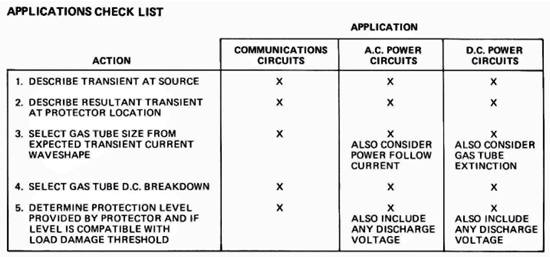
|