| Spark Gaps are basically high energy voltage controlled switching devices. They are unique in their ability to repeatedly switch currents of thousands of amperes, which leads to their most common usage as transient protectors for applications where high energy transient electrical surges are anticipated.
The basic design and operation of a spark gap spark gap is simple. If two metal electrodes are separated by a suitable insulator and a gas placed between the electrodes at a |
|
specific pressure, an electrical breakdown occurs between the electrodes following the application of sufficient voltage across the electrodes. Once formed, this electrical arc is capable of carrying currents of many thousands of amperes while the voltage developed between the electrodes during the arc state remains relatively independent of this arc current. Typically this arc related voltage is in the range of twenty to thirty volts once the breakdown has been initiated. |
|
 |
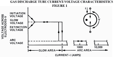
| To initiate the arc in a spark gap, a voltage considerably higher than the arc voltage must be applied. Figure I illustrates the current-voltage characteristic of a typical spark gap. |
|
Figure IL-A shows a basic application for a spark gap used as a protective device. The spark gap is placed across the input terminals of the circuit load to be protected. Because of its high inherent impedance the spark gap is essentially undetected by the normal signal |
| As a voltage is applied across the electrodes of the tube this voltage must be raised until it reaches the initiation point before current begins to flow. This initiation voltage is both a function of the device design and the rate at which the input voltage is applied. Characteristically |
|
voltages, however with the arrival of a transient voltage of sufficient magnitude the spark gap goes into its arc state, thus placing a very low impedance across the load for the duration of the transient. |
|
| spark gaps require higher initiation voltages the more rapidly the input voltage is applied. The first current that flows following initiation is the glow current. Over a narrow band of low amperage currents an associated glow voltage occurs across the electrodes which is essentially independent of current. This low amperage area is called the glow region and it is the normal operational region of the voltage regulator type of spark gap. |
|
Figure lI-B illustrates the same basic application except for a three electrode spark gap on a balanced pair line. It is apparent from the current-voltage characteristics of Figure I that a breakdown or initiation voltage selected for the spark gap must be above the normal signal voltage to prevent unwanted breakdown of the protector. In addition, if the incoming lines include a D.C. voltage, consideration must be given to the current-voltage requirements of the spark gap to allow it to extinguish following initiation of the tube by a transient voltage. |
| Most spark gap protection devices are not designed for operation in this glow region due to the current limitations of the region, but are intended for use in the arc area which occurs as current is provided beyond the glow region.In the application of spark gap spark gaps, two fundamentals from Figure I are of importance. First, the applied voltage must reach the initiation voltage before breakdown can occur and second, in order for the arc to extinguish following the initiation of the breakdown, the voltage curve must be retraced back through the glow area. |
|
Extinction of the are where the source is an AC voltage is relatively direct due to the zero voltage crossover point which occurs with each polarity reversal.
For all but simple communication and data lines, application of spark gaps involves the combination of the spark gap with other circuit devices to fulfill the requirements of the current-voltage relations of the spark gap. For all applications, selection of a spark gap device with the proper current capacity, coordinated with the expected transient, is required. |
|
| |
|
| |
Examples of the combination of spark gaps with other circuit devices are as follows. These coordinated circuit protectors are hybrids and may be specified and packaged as a complete system.
For D.C. systems whose normal voltage and power supply short circuit current are adequate to hold the spark gap in the arc or glow area, a series resistance must be provided with the spark gap. Either a resistor having a high current capability or a varistor may be used. The resistance element must drop |
|
sufficient system voltage to bring the across -the -electrode voltage below the glow voltage curve for the spark gap once the transient voltage has passed. Several resistance-spark gap combinations may be placed in parallel to lower the transient
voltage developed across the resistance elements.
For AC systems with a large source power capability, a resistance element may be placed in series with the spark gap to lessen the current duty required of the spark gap until the next current zero is reached and extinction occurs. |
|
 |
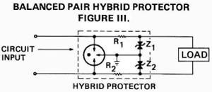
For solid state systems having a low voltage damage threshold, a second stage of protection using a device whose current capability is less than the spark gap, but which has a lower initiation voltage may be used. An example of such a device is the hybrid combination of a zener diode and a spark gap shown in Figure III for a balanced pair line.
The resistances, R1 ad R2, limit the current through each |
|
zener diode until the spark gap discharges. There are many combinations of circuit elements which may be used with the spark gaps for specific applications.
Reynolds Industries offers the assistance of their Application Engineering Group to provide technical help with specific applications. Complete hybrid packages designed specifically for your application can also be supplied. |
|
 |
|


