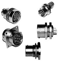
| Items |

167-9708
7 Pin Bayonet, Shielded Plug Cable Assembly
|

167-9709
7 Pin Bayonet, Non-Shielded Plug Cable Assembly
|

167-9715
Double Ended Shielded Plug Cable Assembly
|

167-9716
Double-Ended Non-Shielded Plug Cable Assembly
|

167-9718
Single Ended Shielded Plug Cable Assembly
|
|
Series
|
N/A
1807
|
|
Number of Contacts
|
N/A
7
|
|
Voltage Rating
|
N/A
15 kVDC
|
|
Altitude Rating
|
N/A
70,000 ft
|
|
Operating Temperature
|
N/A
-55 to 125 ºC
|
|
Current Rating
|
N/A
7.5 A
|
|
Insulator Material
|
N/A
Silicone
|
N/A
Silicone
|
N/A
|
N/A
|
N/A
|
|
Coupling Style
|
N/A
Bayonet
|
|
Threaded Coupling Available
|
N/A
Yes
|
|
Coupling Nut Material
|
N/A
Aluminum
|
|
Coupling Nut Finish
|
N/A
Nickel
|
|
Body Lubricant
|
N/A
Dry Lube
|
|
Contact Type
|
N/A
Male
|
N/A
Male
|
N/A
|
N/A
|
N/A
|
|
Contact Material
|
N/A
Brass
|
|
Contact Finish
|
N/A
Gold
|
|
Contact Diameter
|
N/A
0.060 in1.52 mm
|
N/A
0.060 in1.52 mm
|
N/A
|
N/A
|
N/A
|
|
Wire Type
|
N/A
Shielded
|
N/A
Non-Shielded
|
N/A
Shielded
|
N/A
Non-Shielded
|
N/A
Shielded
|
|
Wire Insulation
|
N/A
|
N/A
FEP
|
N/A
|
N/A
FEP
|
N/A
FEP
|
|
Braid Termination
|
N/A
Clamp
|
|
Test Voltage at 70,000 ft
|
N/A
22 kVDC
|
|
Accomodates Wire Diameter
|
N/A
|
N/A
0.080 in2.032 mm
|
N/A
0.080 in2.032 mm
|
N/A
0.080 in2.032 mm
|
N/A
0.080 in2.032 mm
|
|
Mating Compatibility
|
N/A
|
N/A
|
N/A
Mates all series 1807 bayonet receptacles
|
N/A
Mates all series 1807 bayonet receptacles
|
N/A
Mates all series 1807 bayonet receptacles
|
|
Panel Mounting Torque
|
N/A
|
|
Pressure Differential Rating
|
N/A
|
|
Maximum Leak Rate (Helium)
|
N/A
|
|
Panel Mounting Style
|
N/A
|
|
Assembly Type
|
N/A
Plug Bag Assembly
|
N/A
Plug Bag Assembly
|
N/A
Double-Ended Plug Cable Assembly
|
N/A
Double-Ended Plug Cable Assembly
|
N/A
Single-Ended Plug Cable Assembly
|
|
END #1
|
N/A
|
N/A
|
N/A
167-9708
|
N/A
167-9709
|
N/A
167-9708
|
|
END #2
|
N/A
|
N/A
|
N/A
167-9708
|
N/A
167-9709
|
N/A
Plain
|
|
Sealed Receptacle
|
N/A
No
|
|
Standard/Non-Standard1
|
N/A
Standard Part
|
|
Cable Assembly Length2
|
N/A
All cable assembly cable lengths are to be specified in inches only. For example, to order part number 178-6027 with a cable length of 10 feet 8 inches the cable assembly part number would be specified as 178-6027-128N.
|
|
Manufacturing Notes
|
N/A
Contact Teledyne Reynold's Engineering to discuss custom designs. Product numbers and specs subject to change without notice. Products listed represent only a small selection of Teledyne Reynold's products please visit www.teledynereynolds.com for the
most up to date product information.
|
|
Part #
|
N/A
167-9346
|
N/A
167-9543
|
N/A
167-9346
|
N/A
167-9543
|
N/A
|
|
Operating Voltage
|
N/A
22 kVDC
|
N/A
21 kVDC
|
N/A
22 kVDC
|
N/A
21 kVDC
|
N/A
|
|
Conductor AWG
|
N/A
22
|
N/A
20
|
N/A
22
|
N/A
20
|
N/A
|
|
Conductor Strands
|
N/A
19/34
|
N/A
19/32
|
N/A
19/34
|
N/A
19/32
|
N/A
|
|
Conductor Plating
|
N/A
SPC
|
N/A
TPC
|
N/A
SPC
|
N/A
TPC
|
N/A
|
|
Insulation Material
|
N/A
FEP
|
N/A
FEP
|
N/A
FEP
|
N/A
FEP
|
N/A
|
|
Insulator Diameter
|
N/A
0.080 in2.03 mm
|
N/A
0.080 in2.03 mm
|
N/A
0.080 in2.03 mm
|
N/A
0.080 in2.03 mm
|
N/A
|
|
Shielding AWG
|
N/A
36
|
N/A
|
N/A
36
|
N/A
|
N/A
|
|
Shielding Plating
|
N/A
SPC
|
N/A
|
N/A
SPC
|
N/A
|
N/A
|
|
Shielding Diameter
|
N/A
0.100 in2.54 mm
|
N/A
|
N/A
0.100 in2.54 mm
|
N/A
|
N/A
|
|
Jacket Material
|
N/A
FEP
|
N/A
|
N/A
FEP
|
N/A
|
N/A
|
|
Jacket Diameter
|
N/A
0.125 in3.18 mm
|
N/A
|
N/A
0.125 in3.18 mm
|
N/A
|
N/A
|
|
Impedance
|
N/A
43 O
|
N/A
|
N/A
43 O
|
N/A
|
N/A
|
|
Attenuation at 400 MHz
|
N/A
10.6 db/100 ft
|
N/A
|
N/A
10.6 db/100 ft
|
N/A
|
N/A
|
|
Capacitance (Nominal) at 1 kHz
|
N/A
31 pF/ft
|
N/A
|
N/A
31 pF/ft
|
N/A
|
N/A
|
|
Assembly Type
|
N/A
|


